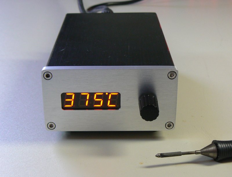
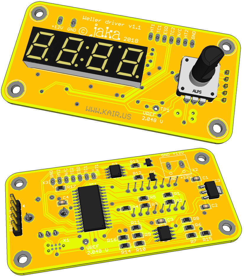
The youtube video used to have captions to describe the meaning
of all the menu settings. However, the captions have disappeared
for unknown reason. I've now gathered operating instructions here.
You can also refer to the menu state diagram further below to help
navigation in the menus.
The basic usage of the soldering station is very simple. When you power it up, it heats up to previously used temperature. You can change the temperature by rotating the knob. The station can be put to standby by pressing the knob.
There is setback mode as in original Weller station. It means
that temperature is reduced to a lower value to preserve tip life
if the station is not used for a while. There is a reed switch on
the handle and a magnet in the stand. When the iron is on the
stand for a predefined time, it goes to reduced setback
temperature. You can revert back to normal operating temperature
by taking the iron from stand or pressing the knob.
If the station is unused for a longer period, it goes into
standby mode. In standby mode the heating is completely off.
Normal operation can be resumed by taking the iron from the stand
or pressing the knob.
Basic setup parameters can be adjusted in setup menu. These parameters have all similar function as the genuine Weller setup parameters. You can enter the setup menu by a long press of the knob, approximately one second.
'bAcc' or Back exits the setup menu and resumes normal
operation
'SEtb' or Setback allows to set the setback temperature.
Default value is 250ºC.
'dELA' or Delay sets the setback time delay in minutes. You
can also set the delay to zero, then the iron goes immediately to
standby when put to stand. You can also disable the setback
feature by turning the delay setting to maximum 'oFF'. Default
value is 5 minutes.
'PoFF' or Power off delay sets power off delay in minutes.
Also this setting can be set to zero or off. However it is not
recommended to set to zero because repeated cooling down and
heating up just puts more stress to the heating element. Default
value is 30 minutes.
'oFSE' or Offset allows to fine tune the iron temperature.
If you have a soldering iron temperature meter or the Weller
calibration tip, you can correct the temperature offset here. If
you don't have any means to measure actual iron temperature, leave
this setting to the default value of 0ºC.
'Unit' sets temperature display unit, either Celsius or
Fahrenheit. Default is Celsius.
'StEP' sets temperature adjustment step size. It can be set
to 1ºC or 5ºC. When in Fahrenheit, the coarse step is 9ºC.
'diAG' or Diagnostics enters the diagnostics and advanced
settings menu level
The diagnostics and advanced settings menu contains diagnostics
information which can be helpful in debugging your newly built
soldering station. It also contains some advanced settings which
are not available in genuine Weller stations.
'bAcc' exits the diagnostics menu and returns to setup
menu
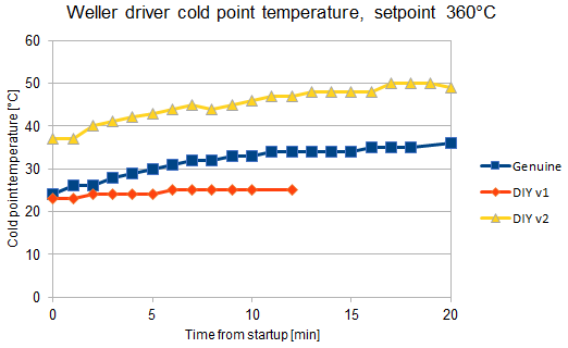
'coLd' shows the cold point compensation temperature. This
is the temperature measured from inside the iron handle, close to
the 3.5 mm jack. This temperature should be close to room
temperature if you have just the handle connected without the tip
(and handle is otherwise cool, that is, not used for some time).
This temperature will rise during normal use, maybe up to 50ºC,
depending on handle type, target tip temperature and ambient
temperature. If the temperature sensor is not connected (e.g.
'poor' mode is enabled), the cold point temperature defaults to
30ºC.
'rEF' allows to fine tune the PIC16F1788 internal voltage
reference. The internal reference can have initial tolerance of up
to ±5%, although I haven't ever seen nowhere near that big errors.
When you enter this menu setting, the reference voltage is
constantly on. You can use a multimeter to measure the reference
voltage from the test point on the Weller driver PCB. Then enter
the measured voltage to this menu setting. The temperature
calculations will then take the reference error into account. Note
that the reference voltage is available on the test point only
when this menu setting is active.
'tyPE' shows the connected tip type which the Weller driver
has identified. Shows 'WMrP' for the soldering pen, 'WMrt' for the
soldering tweezers and 'nc' if nothing is connected. The tip type
is recognized based on the size of resistor in parallel with the
reed switch inside the handle. If the iron is on stand when
powering up, the resistance can't be measured because the reed
switch is shorting the resistor. In this case, the tip type is
recognized by briefly pulsing current to heater 2, and tip type is
recognized based on the response.
'tc 1' and 'tc 2' show unfiltered thermocouple
temperatures. Thermocouple 1 is the WMRP thermocouple or WMRT
right tweezer temperature. Thermocouple 2 is the WMRT left tweezer
temperature.
'dc 1' and 'dc 2' show duty cycles of heating
elements. Duty cycle 1 means again WMRP or WMRT right tweezer
heater duty cycle. Duty cycle 2 is WMRT left tweezer.
'idLE' allows to set a duty cycle value below which is
considered as 'idle'. This is an alternative way of detecting that
the iron is not used. You can use this e.g. if you don't have the
magnet on stand or the reed switch on the handle. If the duty
cycle is below the value set here for duration of setback delay,
it goes to setback temperature. It also further goes into standby
if the duty cycle still stays below this setting for the duration
of power off delay. The station will also revert back to normal
temperature from the setback temperature if the duty cycle
increases higher than this setting. However, if the setback
temperature is very low, it might not be possible to get high
enough duty cycle for resuming. Also from standby you need to
return to normal operation by pressing the knob, since there the
duty cycle will always be 0 because heater is off. You can look at
typical duty cycles in 'dc 1' menu during soldering and inactivity
to help selecting a suitable setting here. If the components you
are soldering are very small, this method probably doesn't work
since the duty cycle is small all the time. You can set this
setting to 0 or 'oFF' to disable this feature, which is the
default setting.
'dCLi' sets a maximum duty cycle for the heaters. Setting a
higher value gives you faster heat-up time and more heating power,
but downside is reduced heating element life. A smaller value
might increase the heater element life but heating is slower and
soldering of large parts becomes more difficult. The default duty
cycle is 58% for 50 Hz mains setting and 50% for 60 Hz mains
setting. When the supply voltage to Weller driver is 12.0 V, the
58% duty cycle gives very similar heat-up speed as the genuine
Weller WD1M, WD2M and WR3M stations. It is highly recommended to
leave this setting to default value. However, if you need more
power to solder something big and heavy, you can briefly increase
this setting at your own risk.
'Poor' allows to enable or disable 'poor mode'. This mode
allows to use a poor mans handle, i.e. just the 3,5 mm stereo
jack. When enabled, the station assumes that a WMRP is always
connected, reed switch is closed and cold point temperature is
30ºC. Despite the name of this mode, it actually works really well
and is completely adequate for hobby users. See more info from
Q&A section on how to connect the 3,5 mm stereo jack in this
mode. The default setting is poor mode off.
'FrEq' sets the mains power frequency. Set this to either
50 Hz or 60 Hz, whichever is used in your country. This setting
affects the temperature measurement timing and filtering. I have
noticed that mains frequency noise coupling to iron cable is the
most common cause for unstable temperature readings from the tip.
The thermocouple produces a tiny, millivolt level voltage which
can be easily ruined by noise coupled to signal. The mains
frequency can be very effectively eliminated by sampling the
temperature at twice the mains frequency, and averaging two
consecutive measurements. It doesn't matter that the sampling is
not actually synced to mains frequency, as the two measurements
will cancel out the error, assuming that it has sinusoidal or
otherwise symmetric shape (which it usually has). Default setting
is 50 Hz.
'vErS' shows the firmware version.

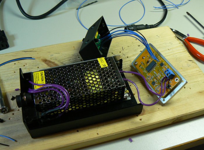
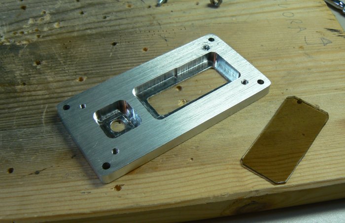
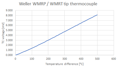
The thermocouple inside the WMRT and WMRP tips seems to be quite
close to D-type thermocouple. On firmware versions up to 0.901 I
was using lookup table based on D-type thermocouple. On newer
firmwares the lookup table is calibrated using Weller K1101
calibration tip. Calibrated TC voltage vs. temperature is shown in
graph below. You can download the data
in excel format from here.
Q: How to connect WMRP / RT tip with 3,5 mm stereo jack?
A: See WMRP pinout from here.
Connect sleeve to 'GND'. Connect ring to 'TC1'. Connect tip to
'HT1'. Use FW v0.6 or newer, enable 'poor' mode from diag menu.
Q: The WMRT tip makes noise! Is this normal?
A: It seems that the heating elements of WMRT make noise when
power is switched on or off rapidly. Earlier firmware versions
used to periodically pulse current to heating element 2 to
recognize tip type. This caused constant buzz with WMRT even when
in standby. FW 0.6 and newer recognizes tip type from resistor in
parallel with reed switch so the noise is reduced. Original Weller
stations drive heating elements using AC and zero point switching.
So the current to tip rises and falls slowly, that's why they
don't make noise.
Q: The temperature reading is not stable like in the Youtube
video, it flickers like there's noise in temperature readout.
Why's that?
A: Most likely some external disturbance is coupled to the iron
cable. The output of the thermocouple is only some millivolts so
it is quite sensitive. WMRT is more sensitive because it has 2k
resistor in series with thermocouple while WMRP has 1k. Especially
mains frequency seems to couple to the thermocouple line. Starting
from firmware v0.6 there is special filtering against mains
frequency noise. Temperature measurements are done at double the
mains frequency interval, and two consecutive measurements are
averaged. This effectively cancels any mains frequency noise. The
diagnostics menu has a setting to select between 50 Hz and 60 Hz
mains frequency, be sure to set it correctly. Another thing which
may help is to connect the ground of the soldering station to
mains ground. The noise might also originate from your power
supply, so you can try to add capacitors at Weller driver supply
voltage input or try different type of power supply.
Q: How can I program the PIC? There is nothing on the PCB to
connect the programmer!
A: See this page for more
information on how to program the PIC in my projects.
Q: I have read and understood the PIC programming instructions
but I still can't program it. The programmer doesn't find the PIC!
A: The ICSP lines on this board are shared with the rotary
encoder. On some encoders, the encoder can keep the one of the
programming lines pulled down even when it is at detent position,
where both switches should be open. Try to rotate the encoder to
such position that neither PGD nor PGC are pulled to GND.
Q: I can only adjust the reference to one direction! Some of the
parameters show '-1' or other erroneous or garbage values!
A: These kind of issues seem to happen if the PIC is programmed
with MPLAB IPE. By default, the MPLAB IPE doesn't seem to erase or
program the data EEPROM. These kind of problems are fixed in
firmware v0.9 and newer. All the parameters are checked at startup
and if any of those are outside of valid range, all parameters are
set to default values.
Q: Can I use the (rare) 24V version of the WMRP tip or WMRT
tweezers with this station?
A: Yes, it is possible. The voltage regulator IC3 needs to
withstand 24V. You should use e.g. UA78M05CDCYR type given in BOM
as alternative type. This has been tested to work.
kair.us/ projects/ weller_driver/
page created 23.12.2015