kair.us/ projects/ nopeustesti/
Sama sivu suomeksi, klikkaa tästä
DIY electronic Speed test

A DIY replica of electronic
speed test game, manufactured by Coinline in Finland. A
similar game is also manufactured by DPS-Promatic in Italy.
These games became very popular in Finland in 90s because they were
part of a tv-show competition. The speed test game is still fun and
addictive. You must press the buttons as they lit up. The speed
gradually increases. See links to videos from below to understand
how it works.
Features
- You can select between speed test and memory test
- Easy and hard modes for speed test. Hard speed test is the
same game but it begins from 100 points. This way you can skip
the slow beginning when trying to beat new high score
- Sound effects as in original game. You can select between old
and new version (old speed games had higher pitch)
- High scores saved, separately for speed test and memory test
- Speed test has 'memory' or 'stack' of 50 presses. So you can
press the buttons a bit late, as long as the sequence is correct
- Demo mode
- Instructions on screen when you switch power on
See this youtube video
of the game in action. Another
video which has the latest version of electronics.
HW
The circuit is based on PIC16F15355 micro controller. Piezo buzzer
and button lights are driven with ULN2003 Darlington array.
7-segment display is driven directly from micro controller pins. It
is possible as long as the used display has high efficiency LEDs.
The display types listed in BOM work well. Switches connect to
ground and their readout uses PIC internal pull-ups.

The PCB uses only though-hole components so it is easy to build by
beginners. It is 2-side PCB with plated through holes so it is
easiest to order the bare PCB from factory. See below section Getting parts. The board has screw
terminals for connecting wires. It is advisable to solder the screw
terminals to bottom side of board, like shown in picture above. Then
you have easy access to those even when the board is attached to
front panel of enclosure.
nopeustesti_v1_circuit_diagram.pdf
Circuit diagram
nopeustesti_v1_assy_and_bom.pdf
Assembly drawing and bill of materials
nopeustesti_v1_hw.zip PCB design
files, made with Eagle 5.12.0
nopeustesti_v1_gerbers.zip
Manufacturing files in Gerber 274-X format
nopeustesti_v1_idf_and_step.zip
3d-model in IDF and STEP formats
FW
Firmware source code and compiled .HEX available below. Compiled
with CCS compiler version 5.081.
nopeustesti_v1_fw_v092.zip
(20.9.2019)
nopeustesti_v1_fw_v093.zip
(28.11.2020)
Instructions
Speed test
Start speed test by pressing red button. You can also start speed
test from score of 100 by pressing yellow button.
Press the buttons as the light up. The game speed increases
gradually. The game has a stack of 50 presses, so you can press
the buttons a bit late. That is, it doesn't matter if the next
button has already lit as long as the sequence is correct. The
game ends when you press wrong button or if you lag 50 presses
behind. Each correct press gives you one point.
Memory test
Start memory test by pressing green button. In memory test, the game
first shows a sequence and then the player must repeat it. The
sequence starts with only one button and length increases by one on
each round. When the player presses the last button of the sequence
that game confirms that with slightly longer sound. Unlike in speed
test, in memory test the sequence can have same button several times
in a row. Each correct press gives you one point.
Changing settings
You can get to setup menu by keeping all the buttons pressed
while switching on the power.
Red button changes sound volume. It has 4 settings. The new
settings is shown on score display.
- 'qUiEt' quiet sound from the piezo buzzer on the PCB.
This is the default setting.
- 'EXtErnAL' sound effects are player from the external
speaker connected to screw terminals. The external speaker has
only this one volume setting.
- 'SoUnd oFF' all sound effects are turned off.
- 'LoUd' loud sound from the piezo buzzer on the PCB.
With this setting, the sound effects are also played from the
external speaker, if connected.
Yellow button changes sound effect type. There are three different
versions. The setting affects both speed test and memory test.
- 'nEW SoUnd' low pitch sound effects as in newer genuine
speed test games. This is the default setting.
- 'mEmory GAmE SoUnd' really high pitch sound effects as
in original memory test game.
- 'oLd SoUnd' high pitch sound effects as in early
original speed test games.
Green button turns demo mode on or off. In demo mode the game slowly
lights the lamps when game is not ongoing. If you use incandescent
bulbs as lights, it's recommended to keep demo mode off, which is
the defalut setting.
Blue (or rightmost) button allows to change light brightness. It
has four settings. The brightness is adjusted with pulse width
modulation (PWM).
- 'diMMESt' this is the dimmest setting. The lamps are
driven with 12.5% duty cycle (that is, the brightness is 12.5%
from the maximum)
- 'diMMer' second dimmest setting. Lamps are driven with
25% duty cycle.
- 'diM' Lamps are driven at 50% duty cycle.
- 'briGht' The brightest setting. Lamps are driven with
constant voltage. This is the default setting.
Exit the setup menu by switching power off. When in setup menu, all
button lights are lit so the game will switch off a little faster.
Clearing high scores
The game remembers the high scores of both the speed test and the
memory test. It is possible to clear the high scores by keeping
both middle buttons pressed while switching on power. The game
will then ask to confirmation to clear the scores. Press red
button to accept, any other to cancel.
Button test
Keep the leftmost and rightmost buttons press while powering up
the game to enter button test. In button test you can test the
button micro switch contact bounce time. Press one button at at
time. When you press it, the display shows contact bounce time in
milliseconds, with accuracy of 0.1 ms. When you release the
button, the display briefly shows the release contact bounce time
in milliseconds. The release contact bounce time is indicated by r
on the left side of the display.
In current firmware version 0.92 there is 15 ms debounce on press
and 5 ms debounce on release. If you get longer contact bounce
times than these in button test, the game will interpret the
contact bounce as new press. This usually means that your game
will end even though you pressed the buttons in correct sequence.
In this case you should replace the failing switch with a better
one. Turn off power to exit the button test mode.
Getting parts
- Order the bare PCB from PCBWay using this
link. Price is ca. $13 for 10 pcs with cheapest shipping.
- Parts for the PCB from e.g. TME in Poland, here is shared cart.
- You can also get some other needed parts from TME. Buttons,
enclosure, power supply and PC sheet, here is shared cart.
- M6 DIN 603 mushroom head square neck bolts, red paint, 6.3 mm
and 4.8 mm Faston connectors, hook-up wire
- You can get the buttons from eBay cheaper than TME. Search
'arcade button led 45mm', or
use this link
- If you don't have PIC programmer, check this for more info
Build
I have used case aluminum enclosure Hammond 1550J.
You can download a milling template from
here. The template is intended to be used with the Hammond
1550J enclosure and 44 mm or 45 mm diameter pushbuttons. The
spacing of buttons is 60 mm as in original game. You can print the
template in 100% size on paper, tape in on the enclosure and use a
punch to mark hole locations.
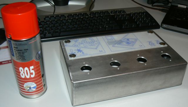
Enclosure with holes waiting to be painted. Holes were made with
milling machine. Artwork will be placed under transparent PC sheet
which is fixed with mushroom head bolts as in original.
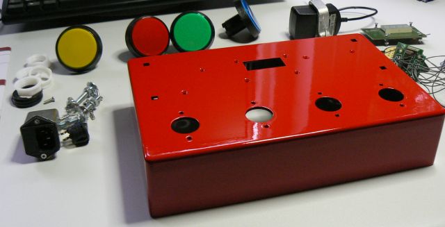
Painted enclosure and parts which will go inside. Picture above
shows 60 mm arcade buttons, but you can use smaller ones. The
original game uses 45 mm buttons.

Here are electronics parts for new version. The buttons above are
from TME, and they have 45 mm diameter.
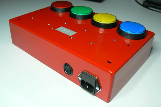
Rear panel has power switch and IEC mains connector with integrated
fuses.
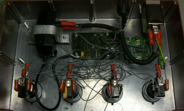
Inside view. I really recommend to use external, approved mains
supply and not place it inside the enclosure. When there's only +12V
DC voltage in the enclosure the risk of electric shock is greatly
reduced. Picture above still shows old version of electronics which
is split to two boards.

The picture above shows wiring diagram of the game. The PCB is seen
from bottom side, as it would be installed to the front panel of the
enclosure. The buttons need to be installed to specific order.
Looking from front, left to right: Red, Yellow, Green and Blue. You
can replace the blue button with white or orange, like the original
speed test games usually have. This is taken into account on front
panel graphics, as the color of the last button is not mentioned.
The wiring diagram above shows button colors in reverse order since
it is drawn as looking from inside of the enclosure.
If your lamps are rated for 5V voltage (rare), you can connect
the common wire of the lamps to screw terminal marked as '5V'
instead of '12V'. This wire is shown in yellow in the wiring
diagram. Most of the LED type lamps need correct polarity in order
to work. Often the polarity is not marked on the lamps, so you
will have to rotate 180 degrees the lamps which don't lit. It's
easier to turn the lamp and not exchange the wiring as the Faston
connectors sit very tight on the lamp holder.
The piezo buzzer on the PCB usually produces loud enough sound
which even when inside the enclosure. You can also connect an
external loudspeaker to screw terminals. The external speaker can
be standard, voice coil type small loudspeaker. The external
speaker must be enabled from the setup menu. There isn't volume
control for the external speaker. You can quieten it by adding a
resistor either in parallel (approx. same size as speaker
impedance) or in series (e.g. some hundreds of ohms) if needed.
If the micro switches you are using have 3 terminals, connect the
wires to ones marked COM and NO. Leave the NC marked not
connected.
You can download the wiring diagram in PDF format by clicking the
image above.

Finished game. You can download the artwork below in .pdf format by
clicking the picture. Original
Inkscape svg -file available here. Note that if you use the
svg file you must also have the K22 Xanthus font installed on your
computer. If you just intend to print the graphics without any
modifications, I recommend to get the PDF version since
it has the fonts embedded.

Modifications and improvements
If you are using adjustable power supply, you can set the
voltage to slightly higher, ca. 13.2 V. This way you can get full
12 V to button lights, because the reverse protection diode D1 and
Darlington array ULN2003 will cause ca. 1.2 V voltage drop.
Alternatively, you can replace D1 with Schottky -type e.g. 1N5815
and IC2 with MOSFET -type e.g. TBD62003APG. You could even replace
D1 with just jumper wire but then you must be careful about
correct polarity. However, difference of one volt is not
significant to button illumination brightness. The used LED type
has much bigger effect, see below.
You get better contrast to score display if you use red or smoked
display lens. It also makes display easier to read in daylight.
The micro switches delivered with the big arcade buttons are usually
crap. The are stiff and have poor contact. It is advisable to
replace those with quality, low force micro switches. E.g. 75
gram Cherry switches or 50
gram E-Switch switches work well. With these, a skilled player
can easily gain tens of points to high score.
Also the LEDs delivered with arcade buttons are usually quite dim.
Good in dusk, but in daylight they could be brighter. I have tested
many types of LEDs and currently the best known LEDs look like this. These LEDs can be even
too bright indoors, therefore firmware v0.92 adds possibility to
adjust light brightness. You can get those e.g. from eBay.
You get best results when you use same color LED as the button
color. When using white leds the color will be pale. More
information on the subject from my LED comparison.
kair.us/ projects/ nopeustesti/
page created 7.8.2013
last updated 10.9.2025 webmaster@kair.us