kair.us/ projects/ pk2m_programmer/
PICkit2- programmer
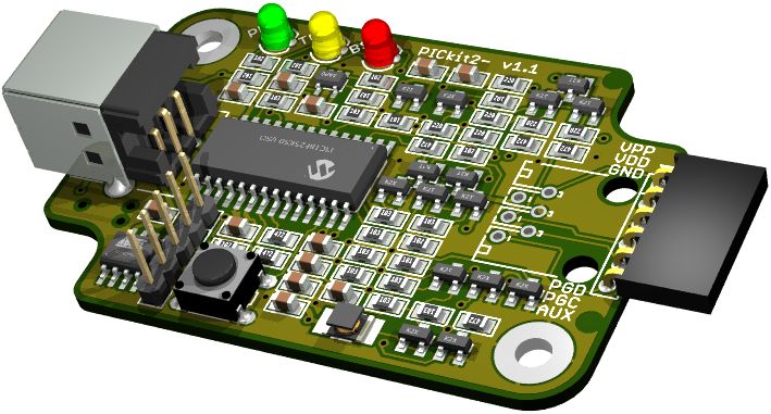
The PICkit2- programmer, PK2M for short, is yet another clone
of the Microchip PICkit2 PIC programmer. The design goal was full
featured clone with reduced BOM. The BOM reduction here means
smaller number of different part types, not smaller total part
count.
Features
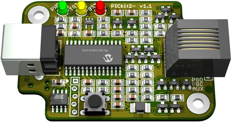
- Compatible with original PICkit2, can be used with MPLAB 8.92
or stand-alone software
- 20 different component types used (original PICkit2 uses 33
different component types)
- Supports all the extra features as the original
(Programmer-to-go, logic tool and UART tool)
- UART tool baud rate improved to 115200 baud, on short bursts
even higher (original PK2 limited to 38400 baud)
- Designed to fit in readily available enclosure
- Flimsy mini-USB replaced with more robust USB B
- Choice of either ICD-style RJ12 or PICkit-style 6-pin socket
strip for ICSP connector
Circuit design
The circuit is based on the original PICkit2 circuit, with some
minor tweaks. The most important change is the microcontroller.
PIC18F2550 is replaced with PIC18F25K50. The K50 is cheaper than the
original. It also supports clock sync to USB, which allows to drop
the crystal and its capacitors, simplifying the BOM. The obvious
downside is that K50 requires different firmware. This isn't a huge
problem, since the original PICkit2 firmware hasn't been updated
since 2008.
Another change is that all the different MOSFETs and diodes have
been replaced with BJTs. For most parts this was simple. But the
target power switch with reverse leakage protection required some
more thought. It is based on the common ideal diode ciruit, which
has been modified to work with PNP instead of PMOS. The total
voltage drop from USB VBUS to target Vdd is very similar as with
original PK2, for currents up to 200 mA.
The original PK2 used comparator interrupts to realize bit-bang
UART. The reason for this was probably that the UART was not thought
at all when the hardware was designed. On PK2M, the hardware UART
pins are connected in parallel to ICSP pins. The hardware UART
allows higher baud rates. The downside is that HW UART pins have
CMOS input levels, so they don't work with low Vdd.
Firmware
The firmware is compiled with C18 compiler as the original. Some
changes were required to adapt to K50. The UART code is modified to
use HW UART, and the UART buffer is increased. VPP feedback divisor
difference is handled in firmware. Support for inverted MCLR_TGT
signal is added (see Variations).
Downloads
pk2m_v11.pdf
Circuit diagram, assembly drawing and bill of materials
pk2m_v11.zip
Eagle 5.12 schematic and board files
pk2m_v11_gerber.zip
Gerber files. You can order the boards from PCBWay using this link.
FirmwareV23200_25K50.zip
Firmware v2.32. Includes source files for both bootloader and
application.
How to build it
I have gathered shared carts for the components. Here is one for TME,
here Mouser
and here Digikey. The TME
card contains also the enclosure, and includes LED spacers and
button with long enough stem. You can order the boards from PCBWay,
or get the gerber files above and order from your favorite PCB
manufacturer. Note that you will need some other PIC programmer to
program the PIC18F25K50.
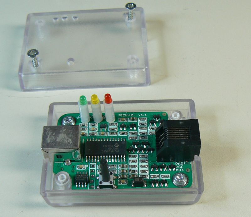
The PK2M circuit board is straightforward to assemble. You need to
decide whether you want to put it in enclosure. If you do, it is
suggested to use 13 mm spacers for the LEDs, and push button with
long stem (total height 17...19 mm from PCB surface). If you use
transparent enclosure, the LED spacers are not mandatory.
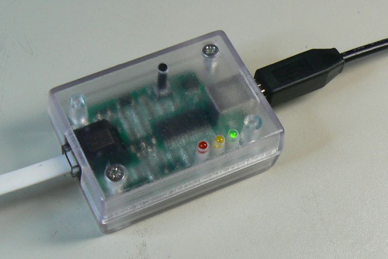
But the enclosure requires some work. The board is designed to fit Kradex
Z24A enclosure, which can be bought from TME.
It is available in different colors. The transparent one, as shown
below, has model number Z24AP
ABS.
This Kradex enclosure is a bit unusual. It comes with two screws for
closing the enclosure, but you need to drill the holes yourself!
Screws for mounting the PCB are not included with enclosure.
Suitable screw is 3x5 mm plastic screw, which is listed in BOM.
Holes for connectors are best done with a coping saw.
Software
Because the PK2M is basically just the plain old PICkit2, its
support hasn't been updated in Microchip official tools for years.
So you can only use it with very old PIC devices using MPLAB.
Newer devices can be programmed with third-party or open source
alternatives. Debugging is only supported in MPLAB. If you plan to
do any serious PIC development, I strongly suggest to get some
newer debugger.
- PICkit-
is the recommended way to use PK2M programmer. It takes
advantage of all features of PK2M.
- PICkit+
should also work with PK2M, although I haven't used it. If you
have, please let me know about it.
- pic32prog
programs PIC32 microcontrollers with many different tools,
including PICkit2 and clones.
- AVRDUDE
programs AVR microcontrollers with many different tools,
including PICkit2 and clones.
- MPLAB
8.92 is the last version of good old MPLAB
- MPLAB-X
IDE supports PICkit2 with old PIC devices, but I can't
recommend using this software. Note that MPLAB-X IPE tool
doesn't support PICkit2 at all.
Variations
Over the years, people have designed different kinds of
simplified PICkit2 clones. You can use pretty much all these
circuit variations with PK2M too. These allow to simplify the
circuit by leaving out components for features you don't need.
Common choices are to leave out EEPROM, which is only needed by
Programmer-to-Go feaure. Or to leave out target VDD adjustment,
which eliminates the opamp and level shift (clamp) transistors.
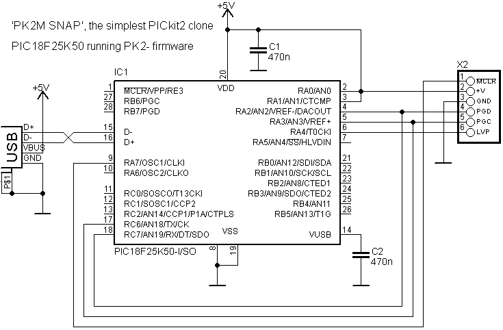
The PK2M firmware implements inverted MCLR_TGT signal. This
allows to make the simplest PICkit2 clone yet, with only 3
components. Because it eliminates also the VPP generator, it only
allows LVP (Low Voltage Programming). So in a way, it is like
'PICkit2 SNAP'. But it could be useful if you want to integrate it
into a bigger design, where it is needed only for a specific use
(e.g. programming a PIC in a production test jig). If you don't
need the UART tool, you can omit the connections to pins 17 and
18. For added protection, you could add 100 ohm resistors to MCLR,
PGD, PGC and LVP lines.
kair.us/ projects/ pk2m_programmer/
page created 13.9.2022
last updated 22.3.2023 webmaster@kair.us


