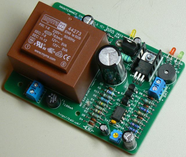
On this page you find all the information needed to build a
maintenance charger for lead-acid batteries. It has protection
against short circuit and reverse connection. The charger has
automatic temperature compensation, unlike most of the popular
CTEK chargers.
One method of maintenance charging is float charging. This means
that the charger produces constant voltage, e.g. 13.8 V, which is
continuously applied to the battery. This means that the battery
is constantly full. At least in theory, this could cause some
unwanted boiling in battery.
This charger stops charging when the battery voltage reaches 13.8
V. The charging starts when voltage drops to 12.6 V. This ensures
that battery is always full enough to prevent from freezing and
sulphation. These voltage switchpoints are temperature
compensated. In 0ºC, the switchpoints are and 14.3 and 13.1 V.
The parts of TME shared project are shown below (M3 screw and nut for TO220 heatsink fixing are not included in in shared project)
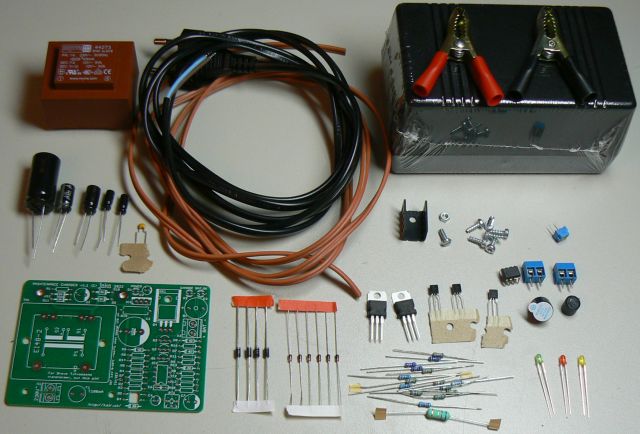
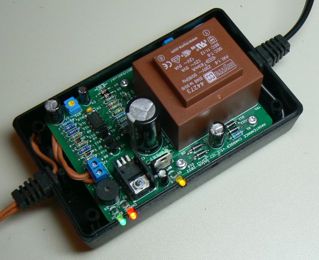
Assembly of the unit is straightforward. The heatsink for transistor doesn't need to be isolated. Leave LED legs long enough, so the LEDs can be bent to side seam of enclosure.
The Myrra transformer can be fixed to PCB with two 3 x 8 mm
plastic screws. The same screws are required to fix the PCB to
enclosure. The enclosure only includes the screws needed to close
the enclosure. Circuit diagram lists alternative PCB transformers
from different manufacturers, but only the Myrra brand has the
screw holes. The other types are held in place only by solder
joints.
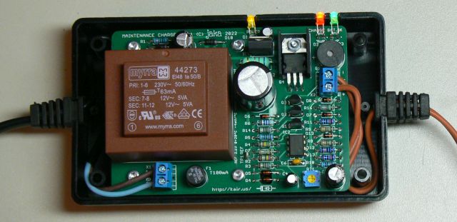
You can route the cables around the posts for added strain
relief. The brown cable is LAPP 0065202,
2x0,75mm2
with silicone insulation. It stays flexible in cold, but the
insulation is easy to tear at sharp edges. It is so soft that you
can strip it with your nails. The PVC mains cable becomes very
stiff when cold.
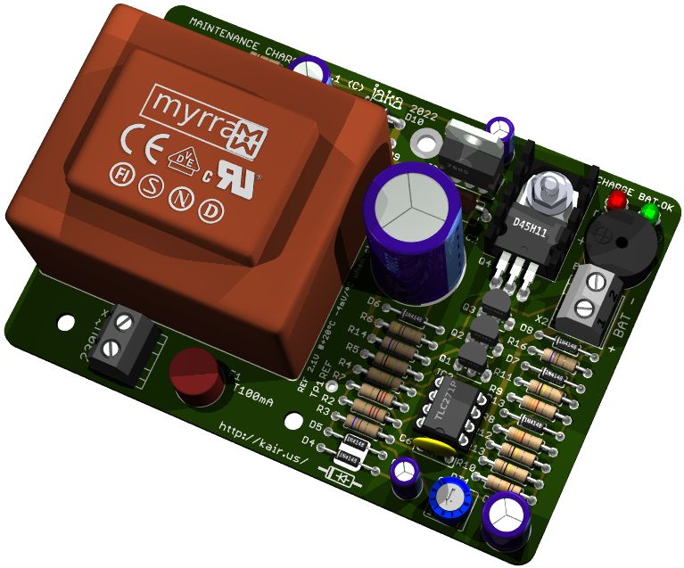
Before use, the voltage threshold needs to be adjusted. Measure
voltage from TP1, and adjust with RT1. Set the voltage to 2.1 V
when charge LED does not light. If ambient temperature is other
than +20ºC, compensate this reading -4 mV/ºC. For example, if the
adjustment is done at 0ºC, adjust TP1 voltage to 2.18 V. The
adjustment is easier if you connect the charger to a full battery,
or if you connect big enough capacitor to output terminals.
Otherwise, the charge LED is off only very briefly. The adjustment
procedure is described on schematic diagram and on bottom of the
board as well. Another tip is to keep the charger powered for some
time, with enclosure closed, before adjustment. This takes the
self heating of charger into account.
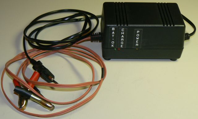
Using the charger is simple. Connect the charger to battery.
Ensure that the green 'BATTERY OK' LED lights. Then connect mains
cable. Ensure that yellow 'POWER' LED lights. All set! The red
'CHARGE' LED indicates that the battery is being charged.
If you are visiting the location where battery/vehicle is stored,
it is worth checking that both yellow and green LEDs are
constantly lit. It indicates that all is OK. If the yellow LED is
off, the charger is not getting power. If the green LED is
flashing, it indicates that connection to battery is not good.