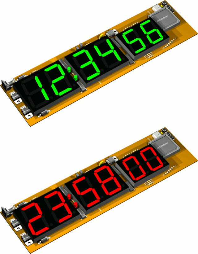
The second version of wall clock is very similar to first version. This version was
designed in 2003, and was awarded with second prize at our student
union HAM club electronics design competition. The main
differences are dual color displays and an etched PCB. The clock
is still derived from a 4 MHz crystal oscillator with no backup
battery, and all logic is implemented in MAX7160 CPLD. The design
shortcuts done on first version are also taken properly into
account, so displays have current limit resistors and there is
location to solder bypass capacitors under the CPLD, even though
not shown in schematics. The displays are Kingbright SBA18-11EGWA
for hours and minutes and SBA15-11EGWA for seconds. The schematic
diagram is available in .pdf below:
Below is an Eagle3d rendered GIF animation of the clock version 2
showing the different colors. Originally the code used PWM to fade
between red and green, but I soon got annoyed as the intermediate
color between pure red and pure green is rather ugly. The final
code changes color at midnight. There was also brainstorming that
the colors could be used to indicate working hours at work or
lecture hours at school.
Unfortunately I couldn't find the source code anymore but I'll
post it here if it pops out somewhere. However it is very similar
to code of the first version.
Difference is support to drive the two common anodes to change
color, and inverted outputs as displays are now common anode and
not common cathode. I and my friends made a total of about five of
these version 2 clocks.
page created 1.8.2014
last updated 1.8.2014 webmaster@kair.us