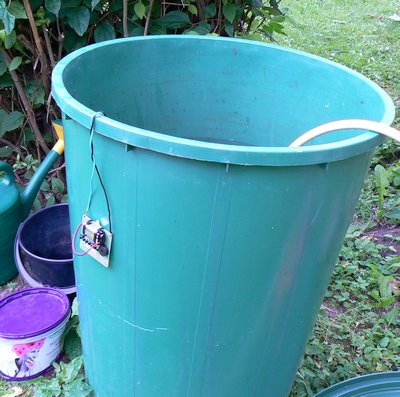
Here is simple water detector you can build yourself. It can be
used for many applications, e.g. leak detector for dishwasher and
other water appliances, alarm that garden watering tank is getting
full etc. It uses only basic components (NPN transistors,
resistors and ceramic capacitors) and runs for years from a 9V
battery.
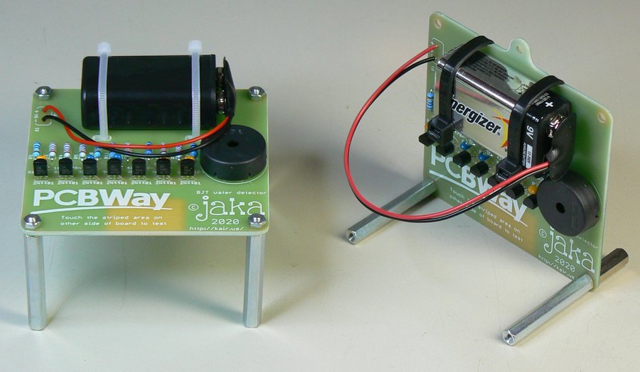
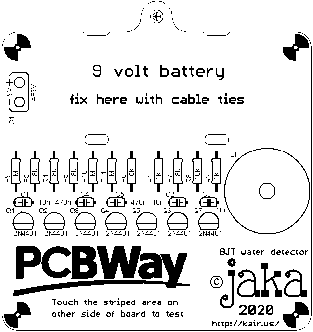
Water detector circuit diagram is shown below. The sensor is a
pattern on the PCB, but also the screw holes are connected in
parallel with the sensor. When water reaches the sensor, small
current flows through it. The current is amplified by Q2 an Q1. R9
ensures the alarm stays off when there isn't water on sensor. You
can increase the sensitivity by increasing R9 and reduce
sensitivity by decreasing R9. Resistor R3 limits current to safe
level if the sensor is short circuited.
Transistors Q3 and Q3 form an astable multivibrator (oscillator).
The frequency is determined by R10, R11, C4 and C5 and is
approximately 1 Hz. The purpose of this oscillator is to provide
intermittent beeping sound, which is more easier to notice than a
continuous sound. It also saves some power because the buzzer is
active only 50% of the time. Transistor Q5 provides more drive
current to supply power to the final stage.
The final stage is another oscillator. It's frequency is set to
ca. 4 kHz to match the resonant frequency of the piezo sounder B1.
If you use some other type of piezo buzzer, check the datasheet
for the resonant frequency! If it is other than 4 kHz, adjust R7,
R8 and/or C2, C3 to get the correct frequency. The piezo elements
will work on wide frequency range, but the sound is the loudest on
resonant frequency. Piezo elements don't like if there is constant
DC voltage over them, but in this circuit it is not a problem
since the power to the final oscillator is completely cut off when
piezo is not making sound.
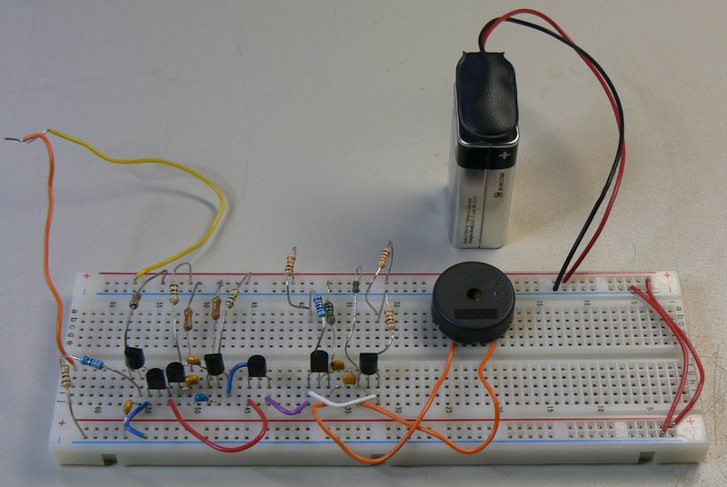
| Description |
Qty |
Parts |
| R METFILM 1k 5% 0.5W 0207 |
2 |
R1, R2 |
| R METFILM 18k 1% 0.5W 0207 |
6 |
R3-R8 |
| R METFILM 1M 5% 0.5W 0207 |
3 |
R9-R11 |
| C CERAM 10 nF X7R RADIAL 5MM PITCH |
3 |
C1-C3 |
| C CERAM 470 nF X7R RADIAL 5MM PITCH |
2 |
C4, C5 |
| TRANSISTOR 2N4401 TO92 |
7 |
Q1-Q7 |
| BUZZER PKM22EPPH4002-B0 MURATA |
1 |
B1 |
| 9V BATTERY SNAP CONNECTOR |
1 |
G1 |
| 150 MM CABLE TIE |
2 |
You can order a batch of 10 boards for $5 + shipping (approx. $13
total) from PCBWay using this
link. If you haven't yet registered to
PCBWay, you can register
via this link. It gives me some PCBWay discount credit,
and also you should get some free bonus in addition to the $5
initial credit which PCBWay nowadays gives for all new users
anyway. You can also use the Gerber package and
order boards from your favorite manufacturer. When ordering, it is
good to leave comment that it is single side board, with bottom
copper, bottom soldermask and top silkscreen. Otherwise you could
get additional questions about it.
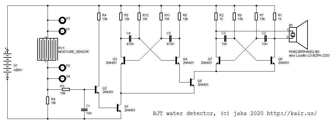
This is easy. Just install the battery and fix it with cable
ties, then place the board to location which you want to monitor.
There are many possible ways how to mount the PCB:
