kair.us/ projects/ hilux_ceiling_light/
Toyota Hilux Vigo ceiling light LED modification
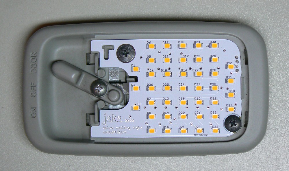
I replaced my Hilux interior light incandescent bulb many years ago
with a LED array PCB. These are available from eBay etc. at very
cheap prices. The advantage is higher light output, as the original
8W bulb is dim. The light tone of these cheap led replacements is
often bad, as the CRI (Color Rendering Index) of cheap leds is poor.
The appearance of the 36 LED array in the middle of the dome light
is also a bit stupid. After some years of use, the leds have started
to fail, and it looks even more stupid. I started to play with idea
of designing an exact fit LED PCB which would fit nicely inside the
OEM light. The target would be to get high lumen output, good CRI,
and high reliability.
Note that even though I designed this LED replacement board for
Hilux, it might suit also other Toyota models, e.g. Fortuner, Hiace
and Tacoma. Also many Corolla models have identical looking interior
light. So if you decide to build this for some other model, compare
your light carefully to pictures on this page first. Also, let me
know if you have successfully used this board on some other vehicle
than Hilux.
The LED drive circuit
It is always good idea to drive LEDs at constant current. There are
a lot of different ways to accomplish this. If you want good
efficiency, you could connect many LEDs in series and drive the
string with current regulating boost converter. This is otherwise
very nice solution, but it lacks redundancy. If one LED fails for
open circuit, all the LEDs in the string would remain dark.
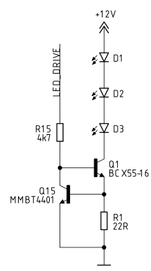
I chose to use simple constant current source using NPN transistors.
The circuit is shown below. The Vbe of Q15 and resistance of R1 sets
the current, which is this case is 0.6 V / 22 Ω = 27 mA. Since
forward voltage of white LED is typically around 3 V, you can't put
more than 3 LEDs in series in a 12 V system. With this circuit, the
LED current stays constant if the car battery voltage varies. It is
quite typical to vary between 10 V ... 14 V. The excess voltage is
'burnt' by the transistor Q1, so it must be able to dissipate the
heat. I wanted a large LED array, so I used a total of 14 instances
the circuit below. This is quite an overkill solution. Nice thing is
that a single component failure will cause only 3 LEDs to go blank.
Also the heat load is shared between many components, so a normal
thin FR4 board suits fine, no need for alucore board or other
cooling solutions.
The delay circuit
The Hilux interior light doesn't have delay (at least mine doesn't).
So I have added a delay circuit, which is shown below. The +12V,
ground and DOOR signals are already available at the ceiling.
When door is opened, the DOOR signal is pulled to ground. This
activates the current source formed by Q32 and Q33, which charges
capacitor C1 with ca. 27 ľA current. The two emitter followers Q30
and Q31 buffer the voltage of C1 and provide the LED_DRIVE signal to
the 14 LED circuits described above. The emitter followers amplify
current, and therefore reduce loading of C1. Otherwise the current
drawn by the LED circuits would drain C1 immediately.
When door is closed, the Q33 shuts off, and capacitor C1 is
discharged through R35. As the voltage of C1 drops, also the
LED_DRIVE signal drops. The LEDs will remain at constant brightness
for some seconds, and then go out slowly.
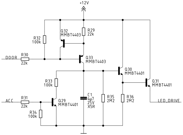
The ACC connection is optional. That signal is not available in the
ceiling. You have to run a wire from some place which has +12V when
ignition key is at ACC or ON position. The purpose of this signal is
to cancel the delay when ignition is on. When ACC is +12V, and DOOR
at GND, the current from Q33 goes through R33. The 27 ľA current
through 100 k resistor sets the voltage at C1 to ca. 2.7 V, which is
enough for the LEDs to light at almost full brightness. When door is
closed, the lights go out slowly, without additional delay. This
mimics the operation of interior lights in new cars, but with analog
electronics instead of the microcontroller driven PWM.
If your car already has a delay, or you otherwise want to disable
the delay, you can just leave out C1.
UPDATE 15.6.2023: If you observe problem that the light does
not turn off at all when you close the door. This might be caused by
some additional load on DOOR signal, caused by e.g. an aftermarket
alarm system. Try to reduce R32 to 22 k or 4k7. This has been
confirmed to fix such issue by one person who built this light
board. Thank you Georgi!
The board
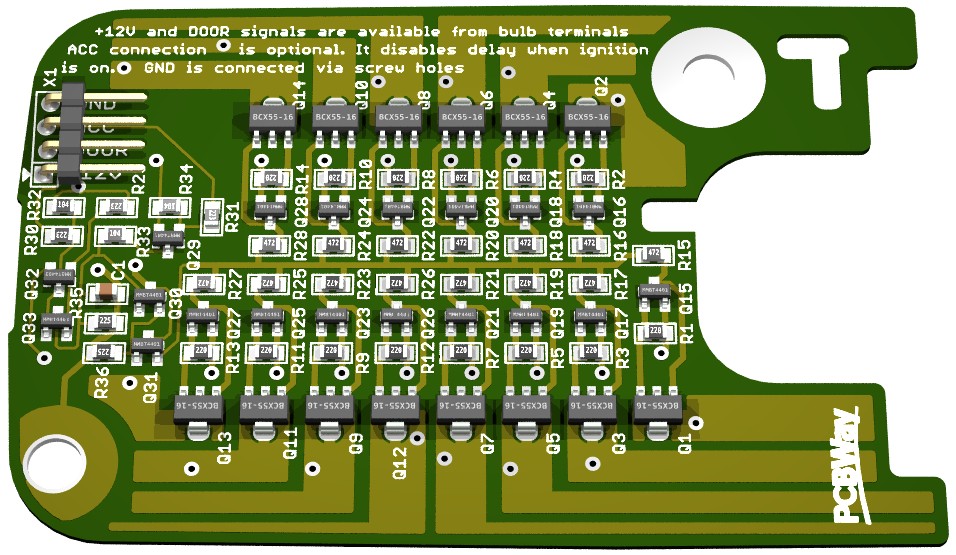
The board is designed to fit into the OEM dome light without any
modifications. It is fixed in place with the 2 original vehicle
screws. I spent quite a bit of time drawing the board outline, but
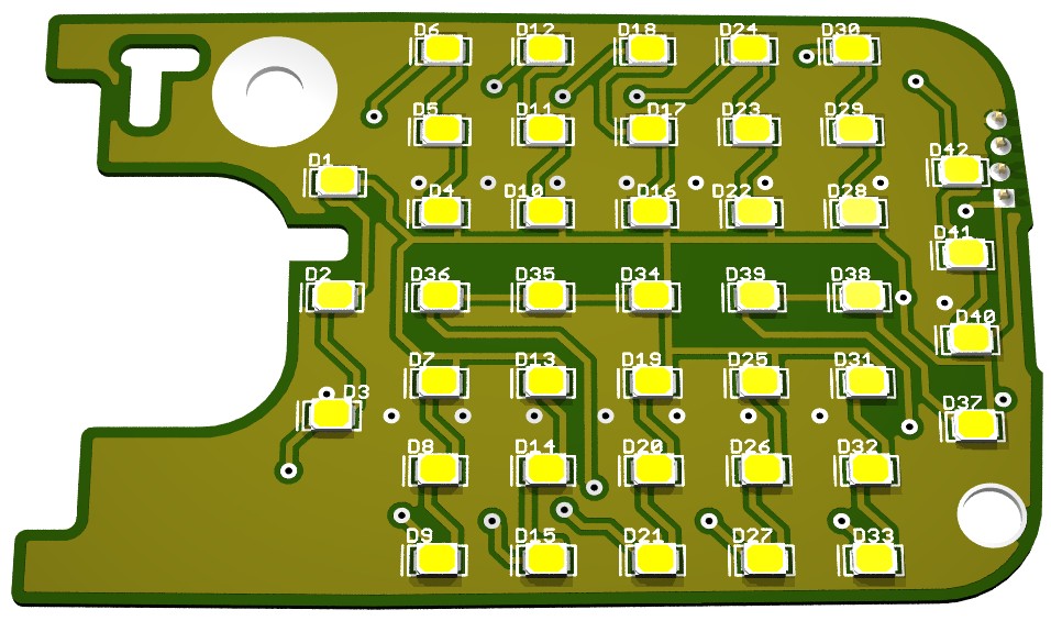
now it's perfect fit. The top side of the board has all the leds, as
can be seen from the Eagle3D / POVray render below. There are some
areas which would still have room for LEDs, but it wouldn't be
possible to place them symmetrically. Symmetrical placement looks
much nicer, otherwise it would look like some of the LEDs were
broken.
All the rest of the circuitry is on bottom side of the board. There
is room for component only on center of the board. The edge areas
are utilized as cooling area for the BCX55-16 medium power
transistors. All resistors and capacitors are 0805 size.
Design files and documentation
hilux_ceiling_light.zip
Eagle 5.12 .sch and .brd
hilux_ceiling_light_gerber.zip
Gerber file package. Click
here to order these boards directly from PCBWay! Use 0.8 mm
board thickness.
hilux_ceiling_light_circuit_diagram.pdf
Circuit diagram in PDF format
hilux_ceiling_light_assy_dwg.pdf
Assembly drawing.
Includes also bill of materials with Digi-Key part numbers. Click here for
shared Digi-Key cart with all the parts!
Install instructions
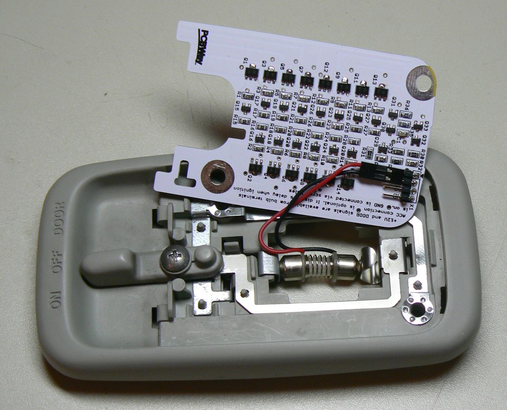
After you have soldered the components, the install is easy. You
should get a 'festoon adapter', it makes connecting quick and easy.
Maybe you could make one from the original bulb if you first burn
the filament with high enough overvoltage and the solder wires to
terminals.
- Set the switch to OFF position.
- Remove the lens. It is easiest to pry open from the switch
hole. Or just pull from switch hole with finger, straight
downwards.
- Remove the old bulb (it is HOT if it has been on!).
- Install the festoon adapter. The red wire should be at switch
end, as shown in picture below
- Remove the two screws with Phillips no. 2 screwdriver. The
lamp might become loose from ceiling, don't worry
- Connect the wires from festoon adapter to connector X1 on PCB.
Red wire to +12V, black wire to DOOR.
- Put the PCB in place, check that the wires don't get squashed
- Make sure that screw holes align with the threads on the roof.
Tighten the lamp and PCB with screws (see picture at top of this
page)
- Now you can test the operation. Note that the delay is
activated also when you turn switch from ON to OFF, so it
doesn't shut off immediately
- If all is OK, put the lens back. Done!
Result and comparisons
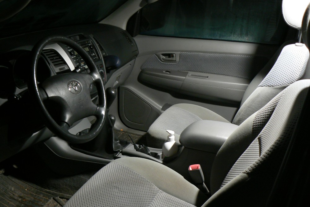
After all your hard work, the reward is improved lighting. The photo
below is taken with my 15 year old digital camera in the middle of
the night, only light comes from the interior dome light. Sharp
picture at ISO100 without flash.
Then a few pictures which try to show how it compares to original
filament bulb and the cheap LED upgrade. The three shots below are
taken with identical shutter speed and aperture settings.

The two shots below compare the light distribution between the 36
LED array and my design. The input voltage was adjusted low enough
to be able to see the individual LEDs. The 36 LED array has some
dead LEDs but you get the idea. The camera white balance is not
properly adjusted in these photos. The Cree JE2835 4000K LEDs really
look neutral white.

kair.us/ projects/ hilux_ceiling_light/
page created 6.11.2020
last updated 15.6.2023 webmaster@kair.us


